Ручной расчёт установившегося режима методом эквивалентирования
В статье приведено описание метода ручного расчёта сложно-замкнутой электрической сети методом эквивалентирования исходной сложно-замкнутой электрической сети до более простой и удобной для выполнения расчётов.
Теоретические основы
Алгоритм расчёта сети с потерями методом эквивалентирования:
- Расчёт параметров схемы замещения.
- Выбор условно-положительного направления мощностей.
- Расчёт эквивалентных мощностей узлов (эквивалентирование шунтов).
- Эквивалентирование исходной схемы, до фрагмента удобного для расчёта.
- Расчёт перетоков мощностей в эквивалентной схеме.
- Расчёт перетоков мощностей в исходной схеме, выполняется для каждого шага эквивалентирования.
- Нахождение точек потокораздела.
- Расчет полученной разветвленной сети с потерями мощности.
- Расчёт уравнительных перетоков в узлах потокораздела.
- Уточнить мощности шунтов, в соотвествие с новыми уровнями напряжений.
- Повторять с пункта 8 до достижения критерия остановки итерационного процесса.
Пример расчёта сложно-замкнутой электрической сети
Задание
Основные задачи расчёта:
- Выполнить расчёт распределения потоков мощностей с учётом потерь мощности методом эквивалентирования.
- Показать «качественную» оценку векторной диаграммы напряжений и токов (без соблюдения точного масштаба углов напряжений).
Исходные данные
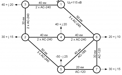
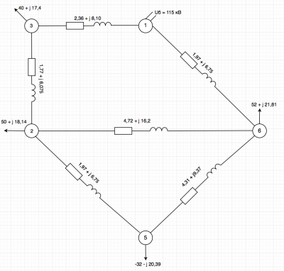
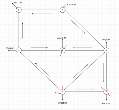
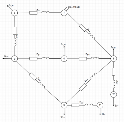
- Исходная схема электрической сети представлена на рисунке 1.
- Мощности нагрузок узлов:
- [math]\displaystyle \dot S_{2}=30+j15 \text{ МВА }; [/math]
- [math]\displaystyle \dot S_{3}=40+j20 \text{ МВА }; [/math]
- [math]\displaystyle \dot S_{4}=40+j20 \text{ МВА }; [/math]
- [math]\displaystyle \dot S_{5}=-50-j25 \text{ МВА }; [/math]
- [math]\displaystyle \dot S_{6}=20+j10 \text{ МВА }; [/math]
- [math]\displaystyle \dot S_{7}=30+j15 \text{ МВА }. [/math]
- Напряжения базисного узла:[math]\displaystyle \dot{U}_{\text{1}}=115[/math] кВ.
- Марка проводов ЛЭП:
- 1-3: 2хАС-240, 40 км;
- 1-6: 3хАС-240, 50 км;
- 2-3: 2хАС-240, 30 км;
- 2-4: 2хАС-240, 40 км;
- 2-5: 3хАС-240, 50 км;
- 4-6: 2хАС-240, 40 км;
- 5-6: АС-185, 40 км;
- 5-7: АС-120, 20 км;
- 6-7: АС-120, 30 км.
Решение
Расчет параметров схемы замещения
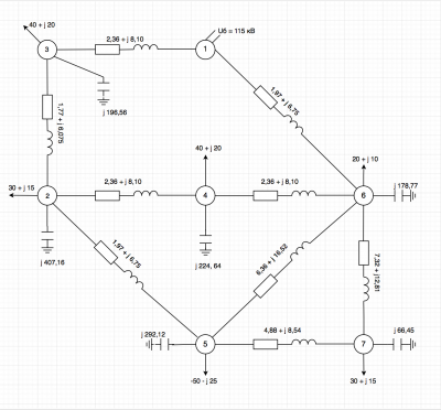
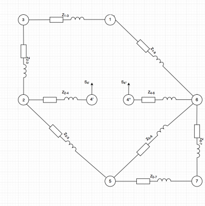
Схема замещения сети и её параметров, приведена на рисунке 2. Расчет параметров для ЛЭП выполнен на основе справочных данных параметров ЛЭП ЛЭП 1-3:
- [math]\displaystyle R_{1-3}=\frac {R_{0} \cdot L_{1-3}}{N} = \frac {0,118 \cdot 40}{2} = 2,36 [/math] Ом;
- [math]\displaystyle X_{1-3}=\frac {X_{0} \cdot L_{1-3}}{N} = \frac {0,405 \cdot 40}{2} = 8,10 [/math] Ом;
- [math]\displaystyle B_{1-3}= B_{0} \cdot L_{1-3} \cdot N = 2,808 \cdot 40 \cdot 2= 224,64 [/math] мкСм.
ЛЭП 1-6:
- [math]\displaystyle R_{1-6}=\frac {R_{0} \cdot L_{1-6}}{N} = \frac {0,118 \cdot 50}{3} = 1,97 [/math] Ом;
- [math]\displaystyle X_{1-6}=\frac {X_{0} \cdot L_{1-6}}{N} = \frac {0,405 \cdot 50}{3} = 6,75 [/math] Ом;
- [math]\displaystyle B_{1-6}= B_{0} \cdot L_{1-6} \cdot N = 2,808 \cdot 50 \cdot 3= 421,20 [/math] мкСм.
ЛЭП 2-3:
- [math]\displaystyle R_{2-3}=\frac {R_{0} \cdot L_{2-3}}{N} = \frac {0,118 \cdot 30}{2} = 1,77 [/math] Ом;
- [math]\displaystyle X_{2-3}=\frac {X_{0} \cdot L_{2-3}}{N} = \frac {0,405 \cdot 30}{2} = 6,075 [/math] Ом;
- [math]\displaystyle B_{2-3}= B_{0} \cdot L_{2-3} \cdot N = 2,808 \cdot 30 \cdot 2= 168,48 [/math] мкСм.
ЛЭП 2-4:
- [math]\displaystyle R_{2-4}=\frac {R_{0} \cdot L_{2-4}}{N} = \frac {0,118 \cdot 40}{2} = 2,36 [/math] Ом;
- [math]\displaystyle X_{2-4}=\frac {X_{0} \cdot L_{2-4}}{N} = \frac {0,405 \cdot 40}{2} = 8,10 [/math] Ом;
- [math]\displaystyle B_{2-4}= B_{0} \cdot L_{2-4} \cdot N = 2,808 \cdot 40 \cdot 2= 224,64 [/math] мкСм.
ЛЭП 2-5:
- [math]\displaystyle R_{2-5}=\frac {R_{0} \cdot L_{2-5}}{N} = \frac {0,118 \cdot 50}{3} = 1,97 [/math] Ом;
- [math]\displaystyle X_{2-5}=\frac {X_{0} \cdot L_{2-5}}{N} = \frac {0,405 \cdot 50}{3} = 6,75 [/math] Ом;
- [math]\displaystyle B_{2-5}= B_{0} \cdot L_{2-5} \cdot N = 2,808 \cdot 50 \cdot 3= 421,20 [/math] мкСм.
ЛЭП 4-6:
- [math]\displaystyle R_{4-6}=\frac {R_{0} \cdot L_{4-6}}{N} = \frac {0,118 \cdot 40}{2} = 2,36 [/math] Ом;
- [math]\displaystyle X_{4-6}=\frac {X_{0} \cdot L_{4-6}}{N} = \frac {0,405 \cdot 40}{2} = 8,10 [/math] Ом;
- [math]\displaystyle B_{4-6}= B_{0} \cdot L_{4-6} \cdot N = 2,808 \cdot 40 \cdot 2= 224,64 [/math] мкСм.
ЛЭП 5-6:
- [math]\displaystyle R_{5-6}=\frac {R_{0} \cdot L_{5-6}}{N} = \frac {0,159 \cdot 40}{1} = 6,36 [/math] Ом;
- [math]\displaystyle X_{5-6}=\frac {X_{0} \cdot L_{5-6}}{N} = \frac {0,413 \cdot 40}{1} = 16,52 [/math] Ом;
- [math]\displaystyle B_{5-6}= B_{0} \cdot L_{5-6} \cdot N = 2,747 \cdot 40 \cdot 1= 109,88 [/math] мкСм.
ЛЭП 5-7:
- [math]\displaystyle R_{5-7}=\frac {R_{0} \cdot L_{5-7}}{N} = \frac {0,244 \cdot 20}{1} = 4,88 [/math] Ом;
- [math]\displaystyle X_{5-7}=\frac {X_{0} \cdot L_{5-7}}{N} = \frac {0,427 \cdot 20}{1} = 8,54 [/math] Ом;
- [math]\displaystyle B_{5-7}= B_{0} \cdot L_{5-7} \cdot N = 2,658 \cdot 20 \cdot 1= 53,16 [/math] мкСм.
ЛЭП 6-7:
- [math]\displaystyle R_{6-7}=\frac {R_{0} \cdot L_{6-7}}{N} = \frac {0,244 \cdot 30}{1} = 7,32 [/math] Ом;
- [math]\displaystyle X_{6-7}=\frac {X_{0} \cdot L_{6-7}}{N} = \frac {0,427 \cdot 30}{1} = 12,81 [/math] Ом;
- [math]\displaystyle B_{6-7}= B_{0} \cdot L_{6-7} \cdot N = 2,658 \cdot 30 \cdot 1= 79,74 [/math] мкСм.
Расчёт эквивалентных мощностей узлов (эквивалентирование шунтов)
Для удобства дальнейших вычислений, выполним расчёт эквивалентных узловых шунтов:
- [math]\displaystyle \underline {Y}_2 = j \frac{ B_{2-3} }{2} + j \frac{ B_{2-4} }{2} + j \frac{ B_{2-5} } {2} = j \frac{1}{2} (168,48 + 224,64 + 421,20) = j 407,16 \text{ мкСм }[/math];
- [math]\displaystyle \underline {Y}_3 = j \frac{ B_{1-3} }{2} + j \frac{ B_{2-3} }{2} = j \frac{1}{2} ( 224,64 + 168,48 ) = 196,56 \text{ мкСм }[/math];
- [math]\displaystyle \underline {Y}_4 = j \frac{ B_{2-4} }{2} + j \frac{ B_{4-6} }{2} = j \frac{1}{2} ( 224,64 + 224,64 ) = 224,64 \text{ мкСм }[/math];
- [math]\displaystyle \underline {Y}_5 = j \frac{ B_{2-5} }{2} + j \frac{ B_{5-6} }{2} + j \frac{ B_{5-7} }{2} = j \frac{1}{2} ( 421,20 + 109,88 + 53,16 ) = 292,12 \text{ мкСм }[/math];
- [math]\displaystyle \underline {Y}_6 = j \frac{ B_{1-6} }{2} + j \frac{ B_{4-6} }{2} + j \frac{ B_{5-6} }{2} + j \frac{ B_{6-7} }{2} = j \frac{1}{2} ( 421,20 + 224,64 + 109,88 + 79,74 ) = 417,73 \text{ мкСм }[/math];
- [math]\displaystyle \underline {Y}_7 = j \frac{ B_{5-7} }{2} + j \frac{ B_{6-7} }{2} = j \frac{1}{2} ( 53,16 + 79,74 ) = 66,45 \text{ мкСм }[/math].
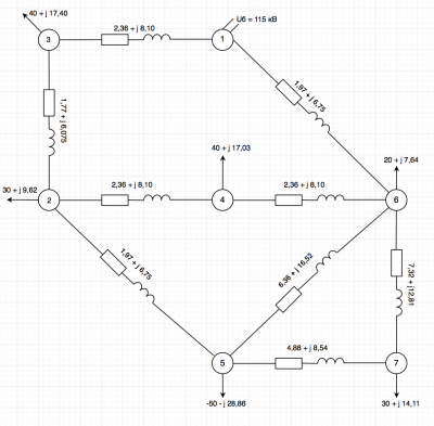
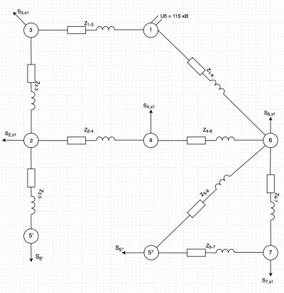
Выполним расчёт потерь в шунтах заданной электрической сети, затем эквивалентируем их в узлы. Результат эквивалентирования узлов представлен на рисунке 3.
Расчёт потерь в шунтах. Задается начальное приближение во всех узлах сети, пусть [math]\dot{U}_{\text{1}}=115 [/math] кВ.
- [math]\displaystyle \Delta \dot S_{ \text{ш2}} = \dot{U_{2}}^{2} \cdot \hat{Y}_2 = 115^{2} \cdot (-j 407,16) \cdot 10^{-6}=-j 5,38 \text{ МВА }[/math];
- [math]\displaystyle \Delta \dot S_{ \text{ш3}} = \dot{U_{3}}^{2} \cdot \hat{Y}_3 = 115^{2} \cdot (-j 196,56) \cdot 10^{-6}=-j 2,60 \text{ МВА }[/math];
- [math]\displaystyle \Delta \dot S_{ \text{ш4}} = \dot{U_{4}}^{2} \cdot \hat{Y}_4 = 115^{2} \cdot (-j 224,64) \cdot 10^{-6}=-j 2,97 \text{ МВА }[/math];
- [math]\displaystyle \Delta \dot S_{ \text{ш5}} = \dot{U_{5}}^{2} \cdot \hat{Y}_5 = 115^{2} \cdot (-j 292,12) \cdot 10^{-6}=-j 3,86 \text{ МВА }[/math];
- [math]\displaystyle \Delta \dot S_{ \text{ш6}} = \dot{U_{6}}^{2} \cdot \hat{Y}_6 = 115^{2} \cdot (-j 178,77) \cdot 10^{-6}=-j 2,36 \text{ МВА }[/math];
- [math]\displaystyle \Delta \dot S_{ \text{ш7}} = \dot{U_{7}}^{2} \cdot \hat{Y}_7 = 115^{2} \cdot (-j 66,45) \cdot 10^{-6}=-j 0,89 \text{ МВА }[/math].
Рассчитаем эквивалентные мощности узлов с учетом потерь в шунтах.
- [math]\displaystyle \dot S_{ 2,\text{Э1} } = \dot S_{2} + \Delta \dot S_{ \text{ш2}} =30+j15 + (-j 5,38) = 30 + j9,62 \text{ МВА }; [/math]
- [math]\displaystyle \dot S_{ 3,\text{Э1} } = \dot S_{3} + \Delta \dot S_{ \text{ш3}} = 40+j20 + (-j 2,60) = 40 + j17,40 \text{ МВА }; [/math]
- [math]\displaystyle \dot S_{ 4,\text{Э1} } = \dot S_{4} + \Delta \dot S_{ \text{ш4}} = 40+j20 + (-j 2,97) = 40 + j17,03 \text{ МВА }; [/math]
- [math]\displaystyle \dot S_{ 5,\text{Э1} } = \dot S_{5} + \Delta \dot S_{ \text{ш5}} = -50-j25 + (-j 3,86) = -50 -j28,86 \text{ МВА }; [/math]
- [math]\displaystyle \dot S_{ 6,\text{Э1} } = \dot S_{6} + \Delta \dot S_{ \text{ш6}} = 20+j10 + (-j 2,36) = 20 + j7,64 \text{ МВА }; [/math]
- [math]\displaystyle \dot S_{ 7,\text{Э1} } = \dot S_{7} + \Delta \dot S_{ \text{ш7}} = 30+j15 + (-j 0,89) =30 + j14,11 \text{ МВА }. [/math]
Эквивалентирование исходной схемы, до фрагмента удобного для расчёта
Эквивалентирование исходной схемы начинаем с узлов с наименьшим рангом (связей с другими узлами). В нашей схемы это узлы 4, 7 (узлы второго ранга).
Эквивалентирование узла 7
Разнос мощности узла 7.
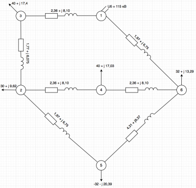
Договоримся, что мощность с одним штрихом относится к узлу с меньшей нумерацией ( т.е в 5), следовательно, с двумя к большей (т.е 6). Результат данного эквивалентирования представлен на рисунке 6.
- [math]\displaystyle \dot S '_{ 7,\text{Э1} } =\dot S_{ 7,\text{Э1} }\cdot \frac {\hat Z_{\text{6-7}}} {{\hat Z_{\text{6-7}}+\hat Z_{\text{5-7}}} } = (30 + j14,11) \cdot \frac {7,32 -j12,81} {7,32 - j 12,81 + 4,88 - j 8,54} = 18,00 + j 8,47 \text{ МВА }; [/math]
- [math]\displaystyle \dot S ''_{ 7,\text{Э1} } =\dot S_{ 7,\text{Э1} }\cdot \frac {\hat Z_{\text{5-7}}} {{\hat Z_{\text{6-7}}+\hat Z_{\text{5-7}}} } = (30 + j14,11) \cdot \frac {4,88 -j8,54} {7,32 - j 12,81 + 4,88 - j 8,54} = 12,00 + j 5,65 \text{ МВА }; [/math]
- [math]\displaystyle \dot S_{ 5,\text{Э2} } = \dot S_{ 5,\text{Э1} } + \dot S '_{ 7,\text{Э1} } = −50−j28,86 + 18,00 + j 8,47 = -32,00 - j 20,39 \text{ МВА }. [/math]
- [math]\displaystyle \dot S_{ 6,\text{Э2} } = \dot S_{ 6,\text{Э1} } + \dot S ''_{ 7,\text{Э1} } = 20+j7,64 + 12,00 + j 5,65 = 32,00 + 13,29 \text{ МВА }. [/math]
Так же необходимо учесть сопротивление линии. Для этого выполним пересчет сопротивления линии (т.к после эквивалентирования узла, разноса мощности, получаем две параллельно идущих ЛЭП)
- [math]\displaystyle \underline Z_{5-6,\text{Э2}} = \frac {(\underline Z_{\text{5-7}} + \underline Z_{\text{6-7}}) \cdot \underline Z_{\text{5-6}}} { (\underline Z_{\text{5-7}} + \underline Z_{\text{6-7}}) + \underline Z_{\text{5-6}} } = \frac {(4,88+ j8,54+ 7,32+ j12,81) \cdot (6,36 + j 16,52)} { (4,88+ j8,54+ 7,32+ j12,81) + (6,36 + j 16,52) } = 4,31 + j 9,38 \text{Ом}. [/math]
Эквивалентирование узла 4
Результат данного эквивалентирования представлен на рисунке 6.
Разнос мощности нагрузки узла 4:
- [math]\displaystyle \dot S '_{ 4,\text{Э3} } =\dot S_{ 4,\text{Э1} }\cdot \frac {\hat Z_{\text{4-6}}} {\hat Z_{\text{2-6}}} = \dot S_{ 4,\text{Э1} }\cdot \frac {\hat Z_{\text{4-6}}} {\hat Z_{\text{2-4}}+ \hat Z_{\text{4-6}}} = (40+j17,03) \cdot \frac {2,36 - j8,10} {2,36 - j 8,10 + 2,36 - j 8,10} = 20 + j8,52 \text{ МВА }; [/math]
- [math]\displaystyle \dot S ''_{ 4,\text{Э3} } =\dot S_{ 4,\text{Э1} }\cdot \frac {\hat Z_{\text{2-4}}} {\hat Z_{\text{2-6}}} = \dot S_{ 4,\text{Э1} }\cdot \frac {\hat Z_{\text{2-4}}} {\hat Z_{\text{2-4}}+ \hat Z_{\text{4-6}}} = (40+j17,03) \cdot \frac {2,36 - j8,10} {2,36 - j 8,10 + 2,36 - j 8,10} = 20 + j8,52 \text{ МВА }; [/math]
- [math]\displaystyle \dot S_{ 2,\text{Э3} } = \dot S_{ 2,\text{Э1} } + \dot S '_{ 4,\text{Э2} } = 30+j9,62 + 20 + j8,52 = 50 + j 18,14 \text{ МВА };[/math]
- [math]\displaystyle \dot S_{ 6,\text{Э3} } = \dot S_{ 6,\text{Э2} } + \dot S ''_{ 4,\text{Э1} } = 32,00 + 13,29 + 20 + j8,52 = 52 + j 21,81 \text{ МВА }. [/math]
Пересчет сопротивления линии ( в данном случае после разноса мощности, соединение ЛЭП последовательно).
- [math]\displaystyle \underline Z_{2-6,\text{Э3}} = \underline Z_{\text{2-4}}+ \underline Z_{\text{4-6}} = 2,36 + j8,10 + 2,36 + j8,10 = 4,72 + j 16,2 \text {Ом}. [/math]
Эквивалентирование узла 5
Результат данного эквивалентирования представлен на рисунке 7.
Разнос мощности нагрузки узла 5:
- [math]\displaystyle \dot S '_{ 5,\text{Э4} } =\dot S_{ 5,\text{Э2} }\cdot \frac {\hat Z_{5-6,\text{Э2}}} {{\hat Z_{5-6,\text{Э2}}+\hat Z_{\text{2-5}}} } = (−32,00−j20,39) \cdot \frac {4,31 - j9,38} {4,31 - j9,38 + 1,79 - j 6,75} = -18,27 - j 13,5 \text{ МВА }; [/math]
- [math]\displaystyle \dot S ''_{ 5,\text{Э4} } =\dot S_{ 5,\text{Э2} }\cdot \frac {\hat Z_{\text{2-5}}} {{\hat Z_{5-6,\text{Э2}}+\hat Z_{\text{2-5}}} } = (−32,00−j20,39) \cdot \frac {1,79 - j 6,75} {4,31 - j9,38 + 1,79 - j 6,75} = -13,73 - j 6,89 \text{ МВА }; [/math]
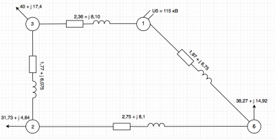
- [math]\displaystyle \dot S_{ 2,\text{Э4} } = \dot S_{ 2,\text{Э3} } + \dot S '_{ 5,\text{Э4} } = 50 + j 18,14 + (-18,27 - j 13,5) = 31,73 + j 4,64 \text{ МВА }; [/math]
- [math]\displaystyle \dot S_{ 6,\text{Э4} } = \dot S_{ 6,\text{Э3} } + \dot S ''_{ 5,\text{Э4} } = 52 +j 21,81 + ( -13,73 - j 6,89 ) = 38,27 + 14,92 \text{ МВА }. [/math]
Пересчет сопротивления линии.
- [math]\displaystyle \underline Z_{2-6,\text{Э4}} = \frac {(\underline Z_{\text{2-5}} + \underline Z_{5-6,\text{Э2}}) \cdot \underline Z_{2-6,\text{Э3}}} { (\underline Z_{\text{2-5}} + \underline Z_{5-6,\text{Э2}}) + \underline Z_{2-6,\text{Э3}} } = \frac {(1,97+ j6,75+ 4,31+ j9,38) \cdot (4,72 + j 16,2)} { (1,97+ j6,75+ 4,31+ j9,38) + (4,72 + j 16,2) } = 2,75 + j 8,1 \text{Ом}. [/math]
Расчет перетоков мощностей в эквивалентной схеме
На данном этапе выполним расчёт перетоков мощностей в эквивалентной схеме. В рассматриваемом нами случае это расчет кольцевой электрической сети без учета потерь мощности.
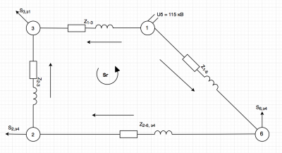
Условно-положительные направления потоков мощностей представлены на Рисунке 8. Для удобства примем мощность ветви 1-3 равной контурной, тогда:
- [math]\displaystyle \dot{S}_{1-3}=\dot{S}_{г}[/math].
В соответствии с первым законом Кирхгофа для узлов (2),(3),(6):
- [math]\displaystyle \dot{S}_{2-3}=\dot{S}_{3,э1}-\dot{S}_{г}[/math];
- [math]\displaystyle \dot{S}_{2-6}=\dot{S}_{2,э4}+\dot{S}_{3,э1}-\dot{S}_{г}[/math].
- [math]\displaystyle \dot{S}_{1-6}=\dot{S}_{6,э4}+ \dot{S}_{2,э4}+\dot{S}_{3,э1}-\dot{S}_{г}[/math];
По второму закону Кирхгофа:
- [math]\displaystyle \Delta\dot{U}_{1-3}-\Delta\dot{U}_{3-2}-\Delta\dot{U}_{2-6}-\Delta\dot{U}_{1-6}=0[/math].
Падение напряжения - произведение тока ветви на её сопротивление:
- [math]\displaystyle \dot{I}_{1-3}\cdot\underline{Z}_{1-3}-\dot{I}_{3-4}\cdot\underline{Z}_{3-2}-\dot{I}_{4-6}\cdot\underline{Z}_{2-6,э4}-\dot{I}_{1-6}\cdot\underline{Z}_{1-6}=0[/math];
- [math]\displaystyle \dot S = \dot U \cdot \hat I[/math].
При допущении, что все напряжение узлов в кольце равны:
- [math]\displaystyle \frac{\hat{S}_{1-3}}{\hat{U}}\cdot\underline{Z}_{1-3}-\frac{\hat{S}_{3-2}}{\hat{U}}\cdot\underline{Z}_{3-2}-\frac{\hat{S}_{2-6}}{\hat{U}}\cdot\underline{Z}_{2-6,э4}-\frac{\hat{S}_{1-6}}{\hat{U}}\cdot\underline{Z}_{1-6}=0[/math];
- [math]\displaystyle \dot{S}_{г}\cdot \hat{Z}_{1-3}=\dot{S}_{2-3}\cdot \hat{Z}_{2-3}+\dot{S}_{2-6}\cdot \hat{Z}_{2-6,э4}+\dot{S}_{1-6}\cdot \hat{Z}_{1-6}[/math].
Выразим и найдем контурный поток:
- [math]\displaystyle \dot{S}_{г} = \frac{\dot{S}_{3,э1}\cdot (\hat{Z}_{2-3}+\hat{Z}_{2-6,э4}+\hat{Z}_{1-6})+\dot{S}_{2,э4}\cdot (\hat{Z}_{2-6,э4}+\hat{Z}_{1-6})+\dot{S}_{6,э4}\cdot \hat{Z}_{1-6}}{\hat{Z}_{1-3}+\hat{Z}_{2-3}+\hat{Z}_{2-6,э4}+\hat{Z}_{1-6}}; [/math]
- [math]\displaystyle \dot{S}_{г}=\frac{(40+j17,4)(1,77-j6,075+2,75-j8,1+1,97-j6,75)+(31,73+j4,64)(2,75-j8,1+ 1,97-j6,75)+(38,27+j14,92)(1,97-j6,75)}{2,36-j 8,1+1,77-j6,075+2,75-j 8,1+1,97-j6,75}; [/math]
- [math]\displaystyle \dot{S}_{г}=53,99+j18,63 МВА[/math]
Найдем потоки по всем линиям кольца:
- [math]\displaystyle \dot{S}_{1-3}=\dot{S}_{k} = 53,99 + j18,63[/math] МВА;
- [math]\displaystyle \dot{S}_{2-3}=\dot{S}_{3,э1}-\dot{S}_{г} = 40+j17,4-(53,99+j18,63) = -13,99 - j1,23[/math] МВА;
- [math]\displaystyle \dot{S}_{2-6}=\dot{S}_{2,э4}+\dot{S}_{3,э1}-\dot{S}_{г}= 31,73+j4,64+40+j17,4-(53,99+j18,63) =17,74+j3,41[/math] МВА;
- [math]\displaystyle \dot{S}_{1-6}=\dot{S}_{6,э4}+ \dot{S}_{2,э4}+\dot{S}_{3,э1}-\dot{S}_{г}=38,27+j14,92+31,73+j4,64+40+j17,4-(53,99+j18,63)=56,01+j18,33 МВА.[/math]
Расчет перетоков мощностей в исходной схеме
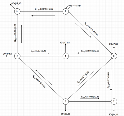
На данном этапе расчёт перетоков выполняется для каждого шага эквивалентирования. Результат расчёта перетолков мощности представлен на рисунке 9.
Возвращение 5 и 4 узла.
Выполним пересчет потока мощности на участке 2-6, с учетом того, что нам известен общий поток мощности, проходящий через две параллельные ЛЭП (2-4-6),(2-5-6)
Уточним:
Сопротивление участка (2-4-6)
- [math]\displaystyle \underline Z_{2-4-6} = \underline Z_{\text{2-4}}+ \underline Z_{\text{4-6}} = 2,36 + j8,10 + 2,36 + j8,10 = 4,72 + j 16,2 \text {Ом};[/math]
Сопротивление участка (2-5-6)
- [math]\displaystyle \underline Z_{2-5-6} = \underline Z_{\text{2-5}} + \underline Z_{5-6,\text{Э2}}= 1,97+ j6,75+ 4,31+ j9,38 = 6,28 + j 16,13 \text {Ом}. [/math]
Выполним пересчет мощности по участкам (2-4-6) и (2-5-6):
- [math]\displaystyle \dot S _{ 2-5-6 } =\dot S_{ 2-6}\cdot \frac {\hat Z_{2-4-6}} {{\hat Z_{2-4-6}+\hat Z_{2-5-6} }} = (17,74 + j3,41) \cdot \frac {4,72 -j16,2} {4,72 - j 16,2 + 6,28 - j 16,13} = 8,83 + j 1,29 \text{ МВА }; [/math]
- [math]\displaystyle \dot S _{ 2-4-6 } =\dot S_{2-6 }-\dot S _{ 2-5-6 } = 17,74 + j3,41 - (8,83 +j1,29)= 8,91+j2,12\text{ МВА }. [/math]
Восстановление 5 узла
- [math]\displaystyle \dot S _{ 5-6,э } =\dot S_{6,э3 }-\dot S _{ 1-6}+\dot S _{ 2-4-6} = 56 + j21,81 - 56,01 - j 18,38 + 8,91 +j2,12 = 8,9+j5,55\text{ МВА }; [/math]
- [math]\displaystyle \dot S _{ 2-5 } = - \dot S _{5-6} + \dot S_{5,э2 }= -8,9-j5,55+(-32,00-j20,39)= 23,1+j14,84\text{ МВА }. [/math]
Восстановление 4 узла
- [math]\displaystyle \dot S _{ 2-4 } =\dot S _{ 2-5}-\dot S_{2,э2 }-\dot S _{ 2-3} = 23,1+j14,84-(30+j9,62)-(-13,99-j1,23)- = 7,09+j6,45\text{ МВА }; [/math]
- [math]\displaystyle \dot S _{ 4-6 } = \dot S _{4,э1} - \dot S_{2-4 }= 40+j17,03-(7,09+j6,45)= 32,91+j10,58\text{ МВА }.[/math]
Восстановление 7 узла
Выполним пересчет мощности по участкам (5-6) и (5-7-6), т.к это два параллельно идущие ЛЭП с рассчитаны ранее нами общим перетоком мощности
- [math]\displaystyle \dot S _{ 5-6,э } = 8,9+j5,55\text{ МВА }; [/math]
- [math]\displaystyle \dot S _{5-7-6 } =\dot S_{ 5-6}\cdot \frac {\hat Z_{5-6}} {{\hat Z_{5-6}+\hat Z_{5-7-6} }} = (8,9 + j5,55) \cdot \frac {6,36 -j16,52} {6,36 -j16,52 + 4,88 - j 8,54 +7,32 -j12,81} = 3,93 +j1,99 \text{ МВА }; [/math]
- [math]\displaystyle \dot S _{ 5-6 } =\dot S_{5-6,э}-\dot S _{ 5-7-6 } = 8,9+j5,55 - (3,93 +j1,99)= 4,97+j3,56\text{ МВА }. [/math]
- [math]\displaystyle \dot S _{ 5-7} =-\dot S_{5,э1}-\dot S _{ 5-6 }-\dot S _{ 2-5 } = -(-50-j28,86)-(23,1+j14,84)-(4,97+j3,56)= 21,93+j10,46\text{ МВА }. [/math]
- [math]\displaystyle \dot S _{ 6-7} =\dot S_{7,э1}-\dot S _{ 5-7 } = 30+j14,11-(21,93+j10,46)= 8,07+j3,65\text{ МВА }. [/math]
Нахождение точек потокораздела
Выбор точек потокораздела выбирается самостоятельно, с учетом того, чтоб дальнейший расчёт радиальной электрической сети был наиболее оптимальный.
Расчет полученной разветвленной сети с потерями мощности
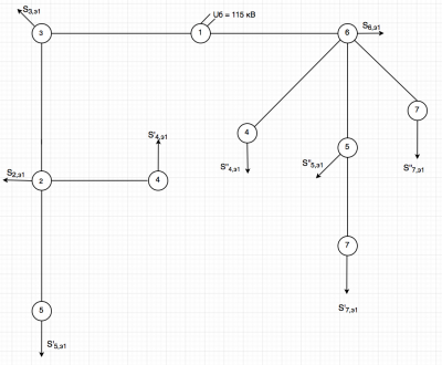
Расчет начинается с выбора условно положительного направления мощностей, представлены на рисунке 11. Задается начальное приближение во всех узлах сети, пусть [math]\dot{U}_{\text{1}}=115[/math] кВ.
Исходные данные для расчёта радиальной сети уточним:
- [math]\displaystyle \dot S_{ 2,\text{Э1} } = 30 + j9,62 \text{ МВА }; [/math]
- [math]\displaystyle \dot S_{ 3,\text{Э1} } =40 + j17,40 \text{ МВА }; [/math]
- [math]\displaystyle \dot S_{ 4',\text{Э1} } = \dot S_{2-4} = 7,09+j6,45\text{ МВА }; [/math]
- [math]\displaystyle \dot S_{ 4'',\text{Э1} } = \dot S_{4-6} = 32,91+j10,58 \text{ МВА }; [/math]
- [math]\displaystyle \dot S_{ 5',\text{Э1} } = - \dot S_{2-5} = -23,1-j14,84 \text{ МВА }; [/math]
- [math]\displaystyle \dot S_{ 5'',\text{Э1} } = -\dot S_{5-6}-\dot S_{5-7} = -4,97-j3,56-21,93-j10,46 = -26,9 -j14,02 \text{ МВА }; [/math]
- [math]\displaystyle \dot S_{ 6,\text{Э1} } = 20 + j7,64 \text{ МВА }; [/math]
- [math]\displaystyle \dot S_{ 7',\text{Э1} } = \dot S_{5-7} = 21,93+j10,46 \text{ МВА }. [/math]
- [math]\displaystyle \dot S_{ 7'',\text{Э1} } = \dot S_{6-7} = 8,07+j3,65 \text{ МВА }. [/math]
Выполним прямой ход по мощностям:
Потери в шунтах на данном этапе не учитываем, потому что они уже учтены в узлах. Расчет потоков мощности по элементам сети осуществляется от конца схемы (где подключена нагрузка) к её началу (базисному узлу)
Вычисление потока мощности по линии 2-5':
- [math]\displaystyle \dot S_{ \text{2-5'к}} =\dot S_{5',э2} = -23,1-j14,84 [/math] МВА;
- [math]\displaystyle \Delta \dot S_{ \text{2-5'}} = \frac {{ P_{\text{2-5'к}}}^{2} + { Q_{2-5'к}}^{2}}{\dot {U_{5'}}^{2}} \cdot (R_{2-5}+jX_{2-5}) = \frac {{23,1}^{2}+{14,84}^{2}}{{115}^{2}} \cdot (1,97+j6,75) = 0,11+j0,38 [/math] МВА;
- [math]\displaystyle \dot S_{ \text{2-5'н}} =\dot S_{ \text{2-5'к}}+\Delta \dot S_{ \text{2-5'}}= -23,1-j14,84 + (0,11+j0,38) = -22,99 -j14,46 [/math] МВА.
Вычисление потока мощности по линии 2-4':
- [math]\displaystyle \dot S_{ \text{2-4'к}} =\dot S_{4',э2} = 7,09+j6,45 [/math] МВА;
- [math]\displaystyle \Delta \dot S_{ \text{2-4'}} = \frac {{ P_{\text{2-4'к}}}^{2} + { Q_{2-4'к}}^{2}}{\dot {U_{4'}}^{2}} \cdot (R_{2-4}+jX_{2-4}) = \frac {{7,09}^{2}+{6,45}^{2}}{{115}^{2}} \cdot (2,36+j8,10) = 0,02+j0,06 [/math] МВА;
- [math]\displaystyle \dot S_{ \text{4'-2н}} =\dot S_{ \text{4'-2к}}+\Delta \dot S_{ \text{4'-2}}= 7,09+j6,45 + (0,02+j0,06) = 7,11 + j6,51 [/math] МВА.
Вычисление потока мощности по линии 2-3:
- [math]\displaystyle \dot S_{ \text{2-3к}} =\dot S_{2,э1} +\dot S_{ \text{2-4'н}}+\dot S_{ \text{2-5'н}}=30 + j9,62+7,11 + j6,51+(-22,99 -j14,46)=14,12+j1,67[/math] МВА;
- [math]\displaystyle \Delta \dot S_{ \text{2-3}} = \frac {{ P_{\text{2-3к}}}^{2} + { Q_{2-3к}}^{2}}{\dot {U_{2}}^{2}} \cdot (R_{2-3}+jX_{2-3}) = \frac {{14,12}^{2}+{1,67}^{2}}{{115}^{2}} \cdot (1,77+j6,075) = 0,03+j0,09 [/math] МВА;
- [math]\displaystyle \dot S_{ \text{2-3н}} =\dot S_{ \text{2-3к}}+\Delta \dot S_{ \text{2-3}}= 14,12+j1,67 + 0,03+j0,09 = 14,15 + j1,76 [/math] МВА.
Вычисление потока мощности по линии 1-3:
- [math]\displaystyle \dot S_{ \text{1-3к}} =\dot S_{3,э1} +\dot S_{ \text{2-3н}}=40 + j17,40+14,15 + j1,76=54,15+j19,16[/math] МВА;
- [math]\displaystyle \Delta \dot S_{ \text{1-3}} = \frac {{ P_{\text{1-3к}}}^{2} + { Q_{1-3к}}^{2}}{\dot {U_{3}}^{2}} \cdot (R_{1-3}+jX_{1-3}) = \frac {{54,15}^{2}+{19,16}^{2}}{{115}^{2}} \cdot (2,36+j8,1) = 0,59+j2,02[/math] МВА;
- [math]\displaystyle \dot S_{ \text{1-3н}} =\dot S_{ \text{1-3к}}+\Delta \dot S_{ \text{1-3}}= 54,15+j19,16+ 0,59+j2,02 = 54,74 + j21,18 [/math] МВА.
Вычисление потока мощности по линии 4"-6:
- [math]\displaystyle \dot S_{ \text{4''-6к}} =\dot S_{4'',э1} = 32,91+j10,58 [/math] МВА;
- [math]\displaystyle \Delta \dot S_{ \text{4''-6}} = \frac {{ P_{\text{4''-6к}}}^{2} + { Q_{4''-6к}}^{2}}{\dot {U_{4''}}^{2}} \cdot (R_{4-6}+jX_{4-6}) = \frac {{32,91}^{2}+{j10,58}^{2}}{{115}^{2}} \cdot (2,36+j8,10) = 0,17+j0,59 [/math] МВА;
- [math]\displaystyle \dot S_{ \text{4''-6н}} =\dot S_{ \text{4''-6к}}+\Delta \dot S_{ \text{4''-6}}= 32,91+j10,58 + (0,17+j0,59) = 33,08 + j11,17 [/math] МВА.
Вычисление потока мощности по линии 6-7":
- [math]\displaystyle \dot S_{ \text{6-7''к}} =\dot S_{7'',э1} = 8,07+j3,65 [/math] МВА;
- [math]\displaystyle \Delta \dot S_{ \text{6-7''}} = \frac {{ P_{\text{6-7''к}}}^{2} + { Q_{6-7''к}}^{2}}{\dot {U_{7''}}^{2}} \cdot (R_{6-7}+jX_{6-7}) = \frac {{8,07}^{2}+{3,65}^{2}}{{115}^{2}} \cdot (7,32+j12,81) = 0,03+j0,08 [/math] МВА;
- [math]\displaystyle \dot S_{ \text{6-7''н}} =\dot S_{ \text{6-7''к}}+\Delta \dot S_{ \text{6-7''}}= 8,07+j3,65 + (0,03+j0,08) = 8,1+j3,73 [/math] МВА.
Вычисление потока мощности по линии 5"-7':
- [math]\displaystyle \dot S_{ \text{7'-5''к}} =\dot S_{7',э1} = 21,93+j10,46 [/math] МВА;
- [math]\displaystyle \Delta \dot S_{ \text{7'-5''}} = \frac {{ P_{\text{5''-7'к}}}^{2} + { Q_{5''-7'к}}^{2}}{\dot {U_{7'}}^{2}} \cdot (R_{5-7}+jX_{5-7}) = \frac {{21,93}^{2}+{10,46}^{2}}{{115}^{2}} \cdot (4,88+j8,54) = 0,22+j0,38 [/math] МВА;
- [math]\displaystyle \dot S_{ \text{5''-7'н}} =\dot S_{ \text{5''-7'к}}+\Delta \dot S_{ \text{5''-7'}}= 21,93+j10,46+ (0,22+j0,38) = 22,15 + j10,84 [/math] МВА.
Вычисление потока мощности по линии 5"-6:
- [math]\displaystyle \dot S_{ \text{5''-6к}} =\dot S_{5'',э1}+\dot S_{ \text{7'-5''н}} = −26,9−j14,02+22,15 + j10,84= -4,75-j3,18 [/math] МВА;
- [math]\displaystyle \Delta \dot S_{ \text{5''-6}} = \frac {{ P_{\text{5''-6к}}}^{2} + { Q_{5''-6к}}^{2}}{\dot {U_{5''}}^{2}} \cdot (R_{5-6}+jX_{5-6}) = \frac {{-4,75}^{2}+{-3,18 }^{2}}{{115}^{2}} \cdot (6,36+j16,52) = 0,02+j0,04 [/math] МВА;
- [math]\displaystyle \dot S_{ \text{5''-6н}} =\dot S_{ \text{5''-6к}}+\Delta \dot S_{ \text{5''-6}}= -4,75-j3,18+ (0,02+j0,04) = -4,73 - j3,14 [/math] МВА.
Вычисление потока мощности по линии 1-6:
- [math]\displaystyle \dot S_{ \text{1-6к}} =\dot S_{6,э1}+\dot S_{ \text{5''-6н}}+ \dot S_{ \text{6-7''н}}+\dot S_{ \text{4''-6н}}=20+j7,64 +(-4,73 - j3,14)+8,1+j3,73 +33,08 + j11,17 = 56,45+j19,4[/math] МВА;
- [math]\displaystyle \Delta \dot S_{ \text{1-6}} = \frac {{ P_{\text{1-6к}}}^{2} + { Q_{1-6к}}^{2}}{\dot {U_{6}}^{2}} \cdot (R_{1-6}+jX_{1-6}) = \frac {{56,45}^{2}+{19,4 }^{2}}{{115}^{2}} \cdot (1,97+j6,75) = 0,53+j1,82 [/math] МВА;
- [math]\displaystyle \dot S_{ \text{1-6н}} =\dot S_{ \text{1-6к}}+\Delta \dot S_{ \text{1-6}}= 56,45+j19,4+ (0,53+j1,82) = 56,98 + j21,22 [/math] МВА.
Выполним обратный ход по напряжениям
Расчет напряжений осуществляется от начала схемы (базисного узла) к её концу (где подключена нагрузка)
Расчет напряжения узла 3, выполним расчёт продольного и поперечного падения напряжения
- [math]\displaystyle \Delta \dot U_{ \text{1-3}} = \frac { P_{\text{1-3н}} \cdot R_{1-3} + Q_{\text{1-3н}}\cdot X_{1-3}}{|\dot U_{ \text{1}}|} = \frac {54,74\cdot 2,36 + 21,18 \cdot 8,1}{115} = 2,62 [/math] ;
- [math]\displaystyle δ \dot U_{ \text{1-3}} = \frac { P_{\text{1-3н}} \cdot X_{1-3} - Q_{\text{1-3н}}\cdot R_{1-3}}{|\dot U_{ \text{1}}|} = \frac {54,74 \cdot 8,1 - 21,18 \cdot 2,36}{115} = 3,42 [/math] ;
- [math]\displaystyle \dot U_{3} = \dot U_{1} - \Delta \dot U_{ \text{1-3}} - jδ \dot U_{ \text{1-3}} = 115 - 2,62 - j 3,42 = 112,38 -j3,42 = 112,43 \angle -0,04^\circ [/math] кВ.
Расчет напряжения узла 2, выполним расчёт продольного и поперечного падения напряжения
- [math]\displaystyle \Delta \dot U_{ \text{2-3}} = \frac { P_{\text{2-3н}} \cdot R_{2-3} + Q_{\text{2-3н}}\cdot X_{2-3}}{|\dot U_{ \text{3}}|} = \frac {14,15 \cdot 1,77 + 1,76\cdot 6,075}{112,43} = 0,32 [/math] ;
- [math]\displaystyle δ \dot U_{ \text{2-3}} = \frac { P_{\text{2-3н}} \cdot X_{2-3} - Q_{\text{2-3н}}\cdot R_{2-3}}{|\dot U_{ \text{3}}|} = \frac {14,15\cdot 6,075 - 1,76 \cdot 1,77}{112,43} = 0,74 [/math] ;
- [math]\displaystyle \dot U_{2} = \dot U_{ \text{3}} - \Delta \dot U_{ \text{2-3}} - jδ \dot U_{ \text{2-3}} = 112,43 - 0,32 - j 0,74 = 112,11 -j0,74 = 112,11 \angle -0,007^\circ [/math] кВ.
- [math]\displaystyle \dot U_{2} = 112,11 \angle (-0,04^\circ -0,007^\circ ) = 112,11 \angle - 0,047^\circ [/math] кВ.
Расчет напряжения узла 4', выполним расчёт продольного и поперечного падения напряжения
- [math]\displaystyle \Delta \dot U_{ \text{2-4'}} = \frac { P_{\text{2-4'н}} \cdot R_{2-4} + Q_{\text{2-4'н}}\cdot X_{2-4}}{|\dot U_{ \text{2}}|} = \frac {7,11 \cdot 2,36 + 6,51\cdot 8,10}{106,1} = 0,66 [/math] ;
- [math]\displaystyle δ \dot U_{ \text{2-4'}} = \frac { P_{\text{2-4'н}} \cdot X_{2-4} - Q_{\text{2-4'н}}\cdot R_{2-4}}{|\dot U_{ \text{2}}|} = \frac {7,11\cdot 8,10 - 6,51 \cdot 2,36}{106,1} = 0,4[/math] ;
- [math]\displaystyle \dot U_{4'} = \dot U_{ \text{2}} - \Delta \dot U_{ \text{2-4'}} - jδ \dot U_{ \text{2-4'}} = 112,21 - 0,66 - j 0,4 = 111,55 -j0,4 = 111,55 \angle -0,004^\circ [/math] кВ.
- [math]\displaystyle \dot U_{4'} = 111,55 \angle (-0,004^\circ -0,047^\circ ) = 111,55 \angle - 0,087^\circ [/math] кВ.
Расчет напряжения узла 5', выполним расчёт продольного и поперечного падения напряжения
- [math]\displaystyle \Delta \dot U_{ \text{2-5'}} = \frac { P_{\text{2-5'н}} \cdot R_{2-5} + Q_{\text{2-5'н}}\cdot X_{2-5}}{|\dot U_{ \text{2}}|} = \frac {(−22,99 )\cdot 1,97 + (−14,46)\cdot 6,75}{112,11} = -1,27 [/math] ;
- [math]\displaystyle δ \dot U_{ \text{2-5'}} = \frac { P_{\text{2-5'н}} \cdot X_{2-5} - Q_{\text{2-5'н}}\cdot R_{2-5}}{|\dot U_{ \text{2}}|} = \frac {(−22,99 )\cdot 6,75 - (−14,46) \cdot 1,97}{112,11} = -1,13[/math] ;
- [math]\displaystyle \dot U_{5'} = \dot U_{ \text{2}} - \Delta \dot U_{ \text{2-5'}} - jδ \dot U_{ \text{2-5'}} = 112,11 - (-1,27) -(- j1,13) = 113,38 +j1,13 = 113,39 \angle 0,01^\circ [/math] кВ.
- [math]\displaystyle \dot U_{5'} = 113,39 \angle (0,01^\circ -0,047^\circ ) = 113,39 \angle - 0,037^\circ [/math] кВ.
Расчет напряжения узла 6, выполним расчёт продольного и поперечного падения напряжения
- [math]\displaystyle \Delta \dot U_{ \text{1-6}} = \frac { P_{\text{1-6н}} \cdot R_{1-6} + Q_{\text{1-6н}}\cdot X_{1-6}}{|\dot U_{ \text{1}}|} = \frac {56,98 \cdot 1,97 + 21,22 \cdot 6,75}{115} = 2,22 [/math] ;
- [math]\displaystyle δ \dot U_{ \text{1-6}} = \frac { P_{\text{1-6н}} \cdot X_{1-6} - Q_{\text{1-6н}}\cdot R_{1-6}}{|\dot U_{ \text{1}}|} = \frac {56,98 \cdot 6,75 - 21,22 \cdot 1,97}{115} = 2,98 [/math] ;
- [math]\displaystyle \dot U_{6} = \dot U_{1} - \Delta \dot U_{ \text{1-6}} - jδ \dot U_{ \text{1-6}} = 115 - 2,22 - j 2,98 = 112,78 -j2,98 = 112,82 \angle -0,03^\circ [/math] кВ.
Расчет напряжения узла 4", выполним расчёт продольного и поперечного падения напряжения
- [math]\displaystyle \Delta \dot U_{ \text{4''-6}} = \frac { P_{\text{4''-6н}} \cdot R_{4-6} + Q_{\text{4''-6н}}\cdot X_{4-6}}{|\dot U_{ \text{6}}|} = \frac {33,08 \cdot 2,36 + 11,17\cdot 8,10}{112,82} = 1,49 [/math] ;
- [math]\displaystyle δ \dot U_{ \text{4''-6}} = \frac { P_{\text{4''-6н}} \cdot X_{4-6} - Q_{\text{4''-6н}}\cdot R_{4-6}}{|\dot U_{ \text{6}}|} = \frac {33,08 \cdot 8,10 - 11,17 \cdot 2,36}{112,82} = 2,14 [/math] ;
- [math]\displaystyle \dot U_{4''} = \dot U_{6} - \Delta \dot U_{ \text{4''-6}} - jδ \dot U_{ \text{4''-6}} = 112,82 - 1,49 - j 2,14 = 111,33 -j2,14 = 111,35 \angle -0,02^\circ [/math] кВ.
- [math]\displaystyle \dot U_{4''} = 111,35 \angle (-0,02^\circ -0,03^\circ ) = 111,35 \angle - 0,05^\circ [/math] кВ.
Расчет напряжения узла 7", выполним расчёт продольного и поперечного падения напряжения
- [math]\displaystyle \Delta \dot U_{ \text{6-7''}} = \frac { P_{\text{6-7''н}} \cdot R_{6-7} + Q_{\text{6-7''н}}\cdot X_{6-7}}{|\dot U_{ \text{6}}|} = \frac {8,1 \cdot 7,32+ 3,73\cdot 12,81}{112,82} = 0,95 [/math] ;
- [math]\displaystyle δ \dot U_{ \text{6-7''}} = \frac { P_{\text{6-7''н}} \cdot X_{6-7} - Q_{\text{6-7''н}}\cdot R_{6-7}}{|\dot U_{ \text{6}}|} = \frac {8,1 \cdot 12,81 - 3,73 \cdot 7,32}{112,82} = 0,68 [/math] ;
- [math]\displaystyle \dot U_{7''} = \dot U_{6} - \Delta \dot U_{ \text{6-7''}} - jδ \dot U_{ \text{6-7''}} = 112,82 - 0,95 - j 0,68 = 111,87 -j0,68 = 111,87 \angle -0,006^\circ [/math] кВ.
- [math]\displaystyle \dot U_{7''} = 111,87 \angle (-0,006^\circ -0,03^\circ ) = 111,87 \angle - 0,036^\circ [/math] кВ.
Расчет напряжения узла 5", выполним расчёт продольного и поперечного падения напряжения
- [math]\displaystyle \Delta \dot U_{ \text{5''-6}} = \frac { P_{\text{5''-6н}} \cdot R_{5-6} + Q_{\text{5''-6н}}\cdot X_{5-6}}{|\dot U_{ \text{6}}|} = \frac {(−4,73) \cdot 6,36+ (−3,14)\cdot 16,52}{112,82} = -0,73 [/math] ;
- [math]\displaystyle δ \dot U_{ \text{5''-6}} = \frac { P_{\text{5''-6н}} \cdot X_{5-6} - Q_{\text{5''-6н}}\cdot R_{5-6}}{|\dot U_{ \text{6}}|} = \frac {(−4,73) \cdot 16,52 -(-3,14) \cdot 6,36}{112,82} = -0,52 [/math] ;
- [math]\displaystyle \dot U_{5''} = \dot U_{6} - \Delta \dot U_{ \text{5''-6}} - jδ \dot U_{ \text{5''-6}} = 112,82 - (-0,73) - (-j 0,52) = 113,55 +j0,52 = 113,55 \angle 0,005^\circ [/math] кВ.
- [math]\displaystyle \dot U_{5''} = 113,55 \angle (0,005^\circ -0,03^\circ ) = 113,55 \angle - 0,025^\circ [/math] кВ.
Расчет напряжения узла 7', выполним расчёт продольного и поперечного падения напряжения
- [math]\displaystyle \Delta \dot U_{ \text{5''-7'}} = \frac { P_{\text{5''-7'н}} \cdot R_{5-7} + Q_{\text{5''-7'н}}\cdot X_{5-7}}{|\dot U_{ \text{5''}}|} = \frac {22,15 \cdot 4,88+ 10,84\cdot 8,54}{113,55} = 1,77 [/math] ;
- [math]\displaystyle δ \dot U_{ \text{5''-7'}} = \frac { P_{\text{5-7'н}} \cdot X_{5-7} - Q_{\text{5''-7'н}}\cdot R_{5-7}}{|\dot U_{ \text{5''}}|} = \frac {22,15 \cdot 8,54 - 10,84 \cdot 4,88}{113,55} = 1,2 [/math] ;
- [math]\displaystyle \dot U_{7'} = \dot U_{5''} - \Delta \dot U_{ \text{5''-7'}} - jδ \dot U_{ \text{5''-7'}} = 113,55 - 1,77 - j 1,2 = 111,78 -j1,2 = 111,79 \angle -0,01^\circ [/math] кВ.
- [math]\displaystyle \dot U_{7'} = 111,79 \angle (-0,01^\circ -0,025^\circ ) = 111,79 \angle - 0,035^\circ [/math] кВ.
Расчет уравнительных перетоков в узлах потокораздела
Для поиска уравнительных перетоков в узлах потокораздела необходимо отдельно для каждой точки потокораздела, в нашем случае узла 4,5 и 7 найти эквивалентное сопротивление сети (т.е сопротивление всей исходной сети до данной точки потокораздела)
Поиск уравнительного перетока мощности в узле 4.
Выполним эквивалентирование сопротивлений исходной сети.
Эквивалентируем последовательно соединение сопротивления линий 5-7 и 6-7
[math]\displaystyle \underline Z_{5-7-6} = \underline Z_{\text{5-7}}+ \underline Z_{\text{6-7}} = 4,88 + j8,54 + 7,32 + j12,81 = 12,2 + j21,35 \text {Ом}.[/math]
Далее эквивалентируем параллельное соединение линий 5-6 и 5-7-6
- [math]\displaystyle \underline Z_{5-6,\text{Э}} = \frac {\underline Z_{\text{5-7-6}}\cdot \underline Z_{5-6}} { (\underline Z_{\text{5-7-6}} + \underline Z_{5-6}) } = \frac {(12,2 + j21,35)\cdot (6,36+j16,52) } { 12,2+ j21,35+ 6,36+ j16,52 } =4,31+j9,38 \text{Ом}. [/math]
Далее вновь эквивалентируем последовательно соединенные сопротивления
[math]\displaystyle \underline Z_{2-3-1-6} = \underline Z_{\text{2-3}}+ \underline Z_{\text{3-1}}+\underline Z_{\text{1-6}} = 1,77+ j6,075 + 2,36 + j8,10 + 1,97 + j6,75 = 6,1 + j20,925 \text {Ом}.[/math]
[math]\displaystyle \underline Z_{2-5-6э} = \underline Z_{\text{2-5}}+ \underline Z_{\text{5-6э}} = 1,97+ j6,75 + 4,31 + j9,38 = 6,28 + j16,13 \text {Ом}.[/math]
Эквивалентируем только что рассчитанные сопротивления 2-3-1-6 и 2-5-6э, с учетом того, что они соединены параллельно
- [math]\displaystyle \underline Z_{2-6,\text{Э}} = \frac {\underline Z_{\text{2-3-1-6}}\cdot \underline Z_{2-5-6э}} { (\underline Z_{\text{2-3-1-6}} + \underline Z_{2-5-6э}) } = \frac {(6,1 + j20,925)\cdot (6,28+j16,13) } { 6,1 + j20,925+ 6,28+j16,13 } =3,15+j9,13\text {Ом}.[/math]
Последнее эквивалентирование для поиска уравнительного потока в узлах 4' и 4". Последовательное соединение сопротивлений
- [math]\displaystyle \underline Z_{4'-4''} = \underline Z_{\text{2-6э}}+ \underline Z_{\text{2-4'}}+Z_{\text{4''-6}} = 3,15+ j9,13 + 2,36 + j8,10 + 2,36 + j8,10 = 7,87 + j25,33 \text {Ом}.[/math]
Так как теперь нам известно эквивалентное сопротивление между узлами 4' и 4", мы можем найти уравнительный переток
- [math]\displaystyle \dot S_{ур,4} = \frac{(U_{4'}+U_{4''})\cdot (\hat U_{4'}-\hat U_{4''})}{2\cdot (\hat Z_{4'-4''})} = \frac{(111,55 \angle -0,087^\circ + 111,35 \angle -0,05^\circ )\cdot (111,55 \angle +0,087^\circ - 111,35 \angle +0,05^\circ )} {2\cdot (7,87-j 25,33)} = -0,82+j1,14 МВА [/math]
Условное значение напряжение в начальной схему в узле 4, найдем как среднее:
- [math]\displaystyle \dot U_{4} = \frac{(U_{4'}+U_{4''})}{2} = \frac{(111,55 \angle -0,087^\circ + 111,35 \angle -0,05^\circ )}{2} = 111,45\angle -0,001^\circ кВ [/math]
Поиск уравнительного перетока мощности в узле 5
Выполним эквивалентирование сопротивлений исходной сети.
Эквивалентируем последовательно соединение сопротивления линий 5-7 и 6-7
[math]\displaystyle \underline Z_{5-7-6} = \underline Z_{\text{5-7}}+ \underline Z_{\text{6-7}} = 4,88 + j8,54 + 7,32 + j12,81 = 12,2 + j21,35 \text {Ом}.[/math]
Далее эквивалентируем параллельное соединение линий 5-6 и 5-7-6
- [math]\displaystyle \underline Z_{5-6,\text{Э}} = \frac {\underline Z_{\text{5-7-6}}\cdot \underline Z_{5-6}} { (\underline Z_{\text{5-7-6}} + \underline Z_{5-6}) } = \frac {(12,2 + j21,35)\cdot (6,36+j16,52) } { 12,2+ j21,35+ 6,36+ j16,52 } =4,31+j9,38 \text{Ом}. [/math]
Далее вновь эквивалентируем последовательно соединенные сопротивления
[math]\displaystyle \underline Z_{2-3-1-6} = \underline Z_{\text{2-3}}+ \underline Z_{\text{3-1}}+\underline Z_{\text{1-6}} = 1,77+ j6,075 + 2,36 + j8,10 + 1,97 + j6,75 = 6,1 + j20,925 \text {Ом}.[/math]
[math]\displaystyle \underline Z_{2-6} = \underline Z_{\text{2-4}}+ \underline Z_{\text{4-6}} = 2,36+ j8,10 + 2,36 + j8,10 = 4,72 + j16,2 \text {Ом}.[/math]
Эквивалентируем только что рассчитанные сопротивления 2-3-1-6 и 2-6, с учетом того, что они соединены параллельно
- [math]\displaystyle \underline Z_{2-6,\text{Э}} = \frac {\underline Z_{\text{2-3-1-6}}\cdot \underline Z_{2-6}} { (\underline Z_{\text{2-3-1-6}} + \underline Z_{2-6}) } = \frac {(6,1 + j20,925)\cdot (4,72 + j16,2) } { 6,1 + j20,925+ 4,72 + j16,2 } =2,66+j9,13\text {Ом}.[/math]
Последнее эквивалентирование для поиска уравнительного потока в узлах 5' и 5". Последовательное соединение сопротивлений
- [math]\displaystyle \underline Z_{5'-5''} = \underline Z_{\text{2-6э}}+ \underline Z_{\text{2-5}}+\underline Z_{\text{5-6э}} = 2,66+j9,13 + 1,97 + j6,75 + 4,31+j9,38 = 8,94 + j25,26 \text {Ом}.[/math]
Так как теперь нам известно эквивалентное сопротивление между узлами 5' и 5", мы можем найти уравнительный переток
- [math]\displaystyle \dot S_{ур,5} = \frac{(U_{5'}+U_{5''})\cdot (\hat U_{5'}-\hat U_{5''})}{2\cdot (\hat Z_{5'-5''})} = \frac{(113,39 \angle -0,037^\circ + 113,55 \angle -0,025^\circ )\cdot (113,39 \angle +0,037^\circ - 113,55 \angle +0,025^\circ )} {2\cdot (8,94-j 25,26)} = - 0,71-j0,47 МВА.[/math]
Условное значение напряжение в начальной схему в узле 5, найдем как среднее:
- [math]\displaystyle \dot U_{5} = \frac{(U_{5'}+U_{5''})}{2} = \frac{(113,39 \angle -0,037^\circ + 113,55 \angle -0,025^\circ )} {2} =113,47 \angle -0,0005^\circ кВ.[/math]
Поиск уравнительного перетока мощности в узле 7
Выполним эквивалентирование сопротивлений исходной сети.
Эквивалентируем последовательно соединение сопротивления линий 2-3 и 3-1 и 1-6, и так же сопротивления 2-4 и 4-6
[math]\displaystyle \underline Z_{2-3-1-6} = \underline Z_{\text{2-3}}+ \underline Z_{\text{3-1}}+\underline Z_{\text{1-6}} = 1,77+ j6,075 + 2,36 + j8,10 + 1,97 + j6,75 = 6,1 + j20,925 \text {Ом}.[/math]
[math]\displaystyle \underline Z_{2-4-6} = \underline Z_{\text{2-4}}+ \underline Z_{\text{4-6}} = 2,36+ j8,10 + 2,36 + j8,10 = 4,72 + j16,2 \text {Ом}.[/math]
Далее эквивалентируем параллельное соединение линий 2-6э и 5-2-6
- [math]\displaystyle \underline Z_{2-6,\text{Э}} = \frac {\underline Z_{\text{2-3-1-6}}\cdot \underline Z_{2-4-6}} { (\underline Z_{\text{2-3-1-6}} + \underline Z_{2-4-6}) } = \frac {(6,1 + j20,925)(4,72 + j16,2) } { 6,1 + j20,925+ 4,72 + j16,2 } =2,66+j9,13 \text{Ом}. [/math]
Далее вновь эквивалентируем последовательно соединенные сопротивления
[math]\displaystyle \underline Z_{5-2-6} = \underline Z_{\text{2-6э}}+ \underline Z_{\text{2-5}} = =2,66+j9,13 +1,97+ j6,75 = 4,63 + j15,88 \text {Ом}.[/math]
Далее эквивалентируем параллельное соединение линий 5-2-6 и 5-6
- [math]\displaystyle \underline Z_{5-6,\text{Э}} = \frac {\underline Z_{\text{5-2-6}}\cdot \underline Z_{5-6}} { (\underline Z_{\text{5-2-6}} + \underline Z_{5-6}) } = \frac {(4,63 + j15,88)(6,36 + j16,52) } { 4,63 + j15,88+ 6,36 + j16,52} =2,73+j8,11 \text{Ом}. [/math]
Последнее эквивалентирование для поиска уравнительного потока в узлах 7' и 7". Последовательное соединение сопротивлений
- [math]\displaystyle \underline Z_{7'-7''} = \underline Z_{\text{5-6э}}+ \underline Z_{\text{5-7}}+\underline Z_{\text{6-7}} = 2,73+j8,11 + 4,886 + j8,54 + 7,32+j12,81 = 14,93 + j29,46 \text {Ом}.[/math]
Так как теперь нам известно эквивалентное сопротивление между узлами 7' и 7", мы можем найти уравнительный переток
- [math]\displaystyle \dot S_{ур,7} = \frac{(U_{7'}+U_{7''})\cdot (\hat U_{7'}-\hat U_{7''})}{2\cdot (\hat Z_{7'-7''})} = \frac{(111,79 \angle -0,035^\circ + 111,87 \angle -0,036^\circ )\cdot (111,79 \angle +0,035^\circ - 111,87 \angle +0,036^\circ )} {2\cdot (14,93 - j29,46)} = -0,55-j0,027 МВА.[/math]
Условное значение напряжение в начальной схему в узле 7, найдем как среднее:
- [math]\displaystyle \dot U_{7} = \frac{(U_{7'}+U_{7''})}{2} = \frac{(111,79 \angle -0,035^\circ + 111,87 \angle -0,036^\circ )} {2} = 111,83 \angle -0,0006^\circ кВ.[/math]
Результат первой итерации
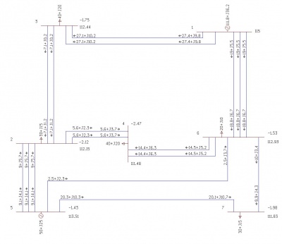
На рисунке 15. представлены результаты ручного расчёта после 1 итерации. На рисунке 16. представлены результаты расчёта RastrWin. Значительное отличие реактивной части объясняется большой погрешностью потерь в шунтах. Получили напряжение в узлах:
- [math]\displaystyle \Delta \dot U_{1} = 115 \text{ кВ }[/math];
- [math]\displaystyle \Delta \dot U_{2} = 112,11 \angle - 0,047^\circ \text{ кВ }[/math];
- [math]\displaystyle \Delta \dot U_{3} = 112,43 \angle -0,04^\circ \text{ кВ }[/math];
- [math]\displaystyle \Delta \dot U_{4} = 111,45\angle -0,001^\circ \text{ кВ }[/math];
- [math]\displaystyle \Delta \dot U_{5} = 113,47 \angle -0,0005^\circ \text{ кВ } [/math];
- [math]\displaystyle \Delta \dot U_{6} = 112,82 \angle -0,03^\circ \text{ кВ }[/math];
- [math]\displaystyle \Delta \dot U_{7} =111,83 \angle -0,0006^\circ \text{ кВ }[/math].
Данные для 2 итерации
Пересчет мощности шунтов, в соотвествие с новыми уровнями напряжений
- [math]\displaystyle \Delta \dot S_{ \text{ш2}} = \dot{U_{2}}^{2} \cdot \hat{Y}_2 = 112,11^{2} \cdot (-j 407,16) \cdot 10^{-6}=-j 5,12 \text{ МВА }[/math];
- [math]\displaystyle \Delta \dot S_{ \text{ш3}} = \dot{U_{3}}^{2} \cdot \hat{Y}_3 = 112,43^{2} \cdot (-j 196,56) \cdot 10^{-6}=-j 2,48 \text{ МВА }[/math];
- [math]\displaystyle \Delta \dot S_{ \text{ш4'}} = \dot{U_{4'}}^{2} \cdot \hat{Y}_4 = 111,55^{2} \cdot (-j 112,32) \cdot 10^{-6}=-j 1,4 \text{ МВА }[/math];
- [math]\displaystyle \Delta \dot S_{ \text{ш4''}} = \dot{U_{4''}}^{2} \cdot \hat{Y}_4 = 111,35^{2} \cdot (-j 112,32) \cdot 10^{-6}=-j 1,39 \text{ МВА }[/math];
- [math]\displaystyle \Delta \dot S_{ \text{ш5'}} = \dot{U_{5'}}^{2} \cdot \hat{Y}_5 = 113,39^{2} \cdot (-j 210,6) \cdot 10^{-6}=-j 2,71 \text{ МВА }[/math];
- [math]\displaystyle \Delta \dot S_{ \text{ш5''}} = \dot{U_{5''}}^{2} \cdot \hat{Y}_5 = 113,55^{2} \cdot (-j 81,52) \cdot 10^{-6}=-j 1,05 \text{ МВА }[/math];
- [math]\displaystyle \Delta \dot S_{ \text{ш6}} = \dot{U_{6}}^{2} \cdot \hat{Y}_6 = 112,87^{2} \cdot (-j 178,77) \cdot 10^{-6}=-j 2,28 \text{ МВА }[/math];
- [math]\displaystyle \Delta \dot S_{ \text{ш7'}} = \dot{U_{7'}}^{2} \cdot \hat{Y}_7 = 111,79^{2} \cdot (-j 26,58) \cdot 10^{-6}=-j 0,33 \text{ МВА }[/math].
- [math]\displaystyle \Delta \dot S_{ \text{ш7''}} = \dot{U_{7''}}^{2} \cdot \hat{Y}_7 = 111,87^{2} \cdot (-j 39,87) \cdot 10^{-6}=-j 0,5 \text{ МВА }[/math].
Начальное приближений напряжений:
- [math]\displaystyle \Delta \dot U_{2} = 112,11 \text{ кВ }[/math];
- [math]\displaystyle \Delta \dot U_{3} =112,43 \text{ кВ }[/math];
- [math]\displaystyle \Delta \dot U_{4'} = 111,55 \text{ кВ }[/math];
- [math]\displaystyle \Delta \dot U_{4''} = 111,35 \text{ кВ }[/math];
- [math]\displaystyle \Delta \dot U_{5'} = 113,39 \text{ кВ }[/math];
- [math]\displaystyle \Delta \dot U_{5''} = 113,55 \text{ кВ }[/math];
- [math]\displaystyle \Delta \dot U_{6} = 112,82 \text{ кВ }[/math];
- [math]\displaystyle \Delta \dot U_{7'} =111,79 \text{ кВ }[/math].
- [math]\displaystyle \Delta \dot U_{7''} = 111,87 \text{ кВ }[/math].
